Antenna Patterns
EMANE supports profile defined antenna using an Antenna Profile Manifest containing a list of all antenna profiles used during an emulation experiment. The manifest is defined using an XML file and specified using the emulator configuration parameter antennaprofilemanifesturi.
The manifest consists of a single <profiles> element that contains one or more <profile> elements.
<!DOCTYPE profiles SYSTEM "file:///usr/share/emane/dtd/antennaprofile.dtd">
<profiles>
  <profile id="1"
           antennapatternuri="/path/to/antenna30dsector.xml"
           blockagepatternuri="/path/to/emanenode/blockageaft.xml">
    <placement north="0" east="0" up="0"/>
  </profile>
  <profile id="2"
           antennapatternuri="/path/to/antenna30dsector.xml">
    <placement north="0" east="0" up="0"/>
  </profile>
</profiles>
Each <profile> element corresponds to a unique antenna profile where:
-
The
idattribute is required and must be unique among all profiles. -
The
antennapatternuriattribute is required and must be specified as an absolute URI. -
The
blockagepatteruriattribute is optional and when specified must be an absolute URI. -
The
<placement>subelement is optional and defines the location of the antenna relative to the platform.
LocationEvents provide the position of the local and remote platforms. The physical layer takes into account local and remote antenna placement when computing the azimuth and elevation between the transmitter and receiver, performing any necessary translation and rotation.
Where:
-
The
northattribute defines the longitudinal offset in meters of the antenna location on the platform. -
The
eastattribute defines the latitudinal offset in meters of the antenna location on the platform. -
The
upattribute defines the vertical offset in meters of the antenna location on the platform.
Defining Antenna Patterns
Antenna pattern XML defines the antenna gain (i.e. radiation pattern) in dBi associated with a given antenna for all elevation and bearing pairs. Antenna pattern elevation and bearing pairs are defined in whole degrees with a maximum of 64800 (180x360) gain values when each pair is defined individually. Antenna patterns support assigning a single gain value to a specified range of elevations and/or bearings to reduce the number of entries required.
Elevation is defined from \([90,-90]\) degrees which corresponds to \(\theta\) from \([0,180]\) degrees. Bearing (azimuth) is defined \([0,360)\) degrees.
An antenna pattern is defined in the platform’s reference frame which is assumed to be pointing (if directional) at an elevation and bearing of 0 degrees. The physical layer will make the proper adjustments to account for platform orientation and antenna pointing when computing gain.
Simple Antenna Patterns
The antenna-omni-24.25dbi.xml antenna pattern used in the bentpipe-02 example is a simple ideal omni antenna with a uniform 24.25dBi gain.
<!DOCTYPE antennaprofile SYSTEM "file:///usr/share/emane/dtd/antennaprofile.dtd">
<!-- omni antenna pattern-->
<antennaprofile>
  <antennapattern>
    <elevation min='-90' max='0'>
      <bearing min='0' max='359'>
        <gain value='24.25'/>
      </bearing>
    </elevation>
  </antennapattern>
</antennaprofile>
emane-guide/examples/antenna-patterns/antenna-omni-24.25dbi.xml
The below 3D rendering of the antenna-omni-24.25dbi.xml pattern uses the tools available in the emane-antenna-simple-viewer project for simple pattern visualization.
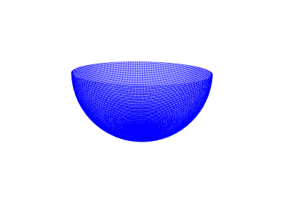
Ideal Omni antenna pattern with uniform 24.5dBi gain: antenna-omni-24.25dbi.xml.
Complex Antenna Patterns
Complex antenna patterns can be created from actual antenna gain pattern measurements. Below are two antenna patterns created from the educational material provided by Antenna Test Lab Co which includes example antenna pattern reports.
Antenna Test Lab Co example 9 is a Surplus Ka Band 38GHz Sector Horn with WR28 Waveguide Port and example 6 is a LHCP omnidirectional antenna designed by Maarten Baert.
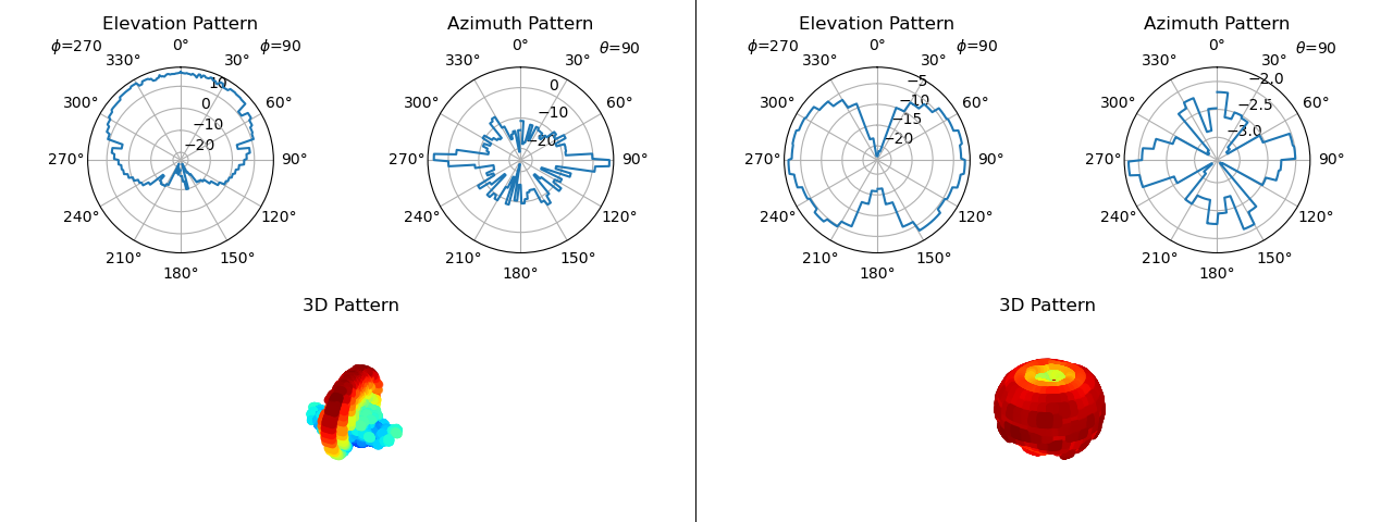
(left) Antenna Test Co Example 9: Ka Band Sector Horn at 40GHz. (right) Antenna Test Co Example 6: LHCP Omnidirectional FPV Antenna at 5.3GHz.
Both antenna pattern XML files are supplied as part of the emane-guide to illustrate complex pattern definitions: ka-band-sector-horn-4000000MHz.xml and lhcp-maarten-baert-pagoda-2-530000MHz.xml.
Below is a snippet of the Ka Band Sector Horn at 40GHz antenna pattern.
<!DOCTYPE antennaprofile SYSTEM "file:///usr/share/emane/dtd/antennaprofile.dtd">
<antennaprofile>
  <!-- Antenna Pattern generated from Antenna Test Lab Co Example 9: Ka Band Sector Horn -->
  <!-- https://antennatestlab.com/antenna-examples/example-9-ka-band-sector-horn-spherical-and-polar-gain-patterns -->
  <antennapattern>
    <elevation min="-90" max="-90">
      <bearing min="0" max="359">
        <gain value="-15.75"/>
      </bearing>
    </elevation>
    <elevation min="-89" max="-85">
      <bearing min="0" max="4">
        <gain value="-14.45"/>
      </bearing>
      <bearing min="5" max="54">
        <gain value="-15.6"/>
      </bearing>
      <bearing min="55" max="59">
        <gain value="-16.75"/>
      </bearing>
      <bearing min="60" max="114">
        <gain value="-16.14"/>
      </bearing>
      <bearing min="115" max="119">
        <gain value="-15.52"/>
      </bearing>
      <bearing min="120" max="169">
        <gain value="-17.3"/>
      </bearing>
      <bearing min="170" max="174">

<... snippet: only 30 lines shown...>
emane-guide/examples/antenna-patterns/ka-band-sector-horn-4000000MHz.xml
Defining Blockage Patterns
Blockage pattern XML defines the blockage associated with a given antenna mounted on a specific platform for all elevation and bearing pairs. The blockage pattern is defined in the platform’s reference frame with the emulator physical layer making adjustments to account for platform orientation. The blockage pattern is optional. When defined, it is used in conjunction with the antenna pattern to determine the actual antenna gain.
The below sample blockage XML file shows full blockage aft (90 degrees <= bearing <= 270 degrees) of the platform and at elevations above and below 10 degrees.
<!DOCTYPE antennaprofile SYSTEM "file:///usr/share/emane/dtd/antennaprofile.dtd">
<!--
 blockage pattern:
  1) entire aft in bearing (90 to 270) blocked
  2) elevation below -10 blocked,
  3) elevation from -10 to -1 is at -10dB to -1 dB 3) elevation from 0 to 90 no blockage
-->
<antennaprofile>
  <blockagepattern>
    <elevation min='-90' max='-11'>
      <bearing min='0' max='359'>
        <gain value='-200'/>
      </bearing>
    </elevation>
    <elevation min='-10' max='-10'>
      <bearing min='0' max='89'>
        <gain value='-10'/>
      </bearing>
      <bearing min='90' max='270'>
        <gain value='-200'/>
      </bearing>
      <bearing min='271' max='359'>
        <gain value='-10'/>
      </bearing>
    </elevation>
    <elevation min='-9' max='-9'>
      <bearing min='0' max='89'>
        <gain value='-9'/>
      </bearing>
      <bearing min='90' max='270'>

<... snippet: only 30 lines shown...>
emane-guide/examples/antenna-patterns/blockageaft.xml
Below is a 3D rendering of the blockageaft.xml blockage pattern.
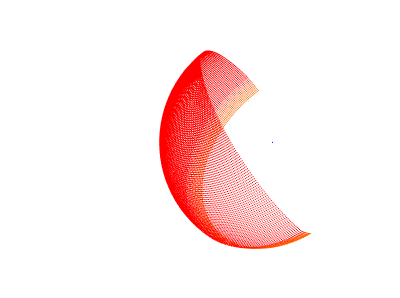
Aft blockage pattern: blockageaft.xml.