Physical Layer
The EMANE physical layer model (physical layer) is central to all emulator functionality. Designed to be flexible and universally used by all radio models, the physical layer is key to providing a realistic emulated electromagnetic operating environment for heterogeneous waveform experimentation.
Features
The physical layer provides the following set of features, some of which are utilized by all radio models while others are only utilized by radio models that are designed and coded for their use: Heterogeneous Model Interaction, Propagation Model, Receive Power Calculation, Antenna Gain, Noise Processing, Frequency Diversity, Collaborative Transmission, Multiple-Input Multiple-Output (MIMO), Fading Model, Spectral Masks, and Spectrum Filters.
Physical layer features are controllable via a combination of start-up and running-state modifiable configuration, events, and control message exchanges with a respective radio model. The physical layer operates in one of two API modes: compatibly mode 1 (compat1) and compatibility mode 2 (compat2).
Compatibility mode 1 is a legacy non-MIMO API mode that supports radio model control messaging for single antenna functionality. This API mode was the sole mode available prior to EMANE 1.3.x. While still supported, the use of this mode by newly developed radio models is deprecated.
Compatibility mode 2 is the newer MIMO API mode and supports radio model control messaging for MIMO. New radio models should use the compatibility mode 2 API, even if not modeling MIMO features. Regardless of the API mode in use, physical layer instances of the same version of EMANE are over-the-air compatible.
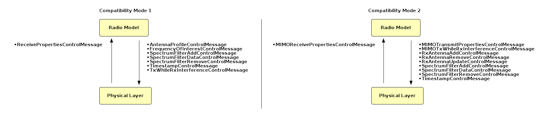
Compatibility Mode Control Messages
Heterogeneous Model Interaction
Physical layer instances are interconnected using an over-the-air multicast channel. All over-the-air transmissions are processed by every emulator instance using the same over-the-air channel. This is how the emulator physical layer accounts for signal propagation, antenna effects and interference sources across heterogeneous radio models.
Each over-the-air transmission has a Common Physical Layer Header prepended. This header is what enables the physical layer to account for spectrum energy from in-band (same) and out-of-band (different) waveform sources.
syntax = "proto2";
package EMANEMessage;
option optimize_for = SPEED;
message CommonPHYHeader
{
  message Transmitter
  {
    required uint32 nemId = 1;
    required double powerdBm = 2;
  }
  message FrequencyGroup
  {
    message FrequencySegment
    {
      required uint64 frequencyHz = 1;
      required uint64 offsetMicroseconds = 2;
      required uint64 durationMicroseconds = 3;
      optional double powerdBm = 4;
    }
    repeated FrequencySegment frequencySegments = 1;
  }
  message TransmitAntenna
  {
    message Pointing
    {
      required uint32 profileId = 1;
      required double azimuthDegrees = 2;
      required double elevationDegrees = 3;
    }
    required uint32 antennaIndex = 1;
    required uint32 frequencyGroupIndex = 2;
    required uint64 bandwidthHz = 3;
    optional double fixedGaindBi = 4;
    optional Pointing pointing = 5;
    optional uint32 spectralMaskIndex = 6;
  }
  required uint32 registrationId = 1;
  required uint32 subId = 2;
  required uint32 sequenceNumber = 3;
  required uint64 txTimeMicroseconds = 4;
  repeated Transmitter transmitters = 5;
  repeated FrequencyGroup frequencyGroups = 6;
  repeated TransmitAntenna transmitAntennas  = 7;
  optional bytes filterData = 8;
}
emane/src/libemane/commonphyheader.proto
As we learn about each physical layer feature, we will highlight what if any information in support of that feature is contained in the Common Physical Layer Header. The following header contents are used in general to identify and process an over-the-air message:
-
registrationId: Identifies the over-the-air transmission as being an emulator physical layer message. -
subId: Identifies the over-the-air transmission as being from an in-band or out-of-band waveform. An over-the-air message matching thesubidconfiguration parameter of the receiver and using frequencies that match thefrequencyofinterestconfiguration parameter or the frequency of interest set associated with a receive antenna configured via control message , is considered in-band. -
sequenceNumber: Unique sequence number incremented for every over-the-air transmission. -
txTimeMicroseconds: over-the-air start-of-transmission (SOT) time stamp.
Propagation Model
Pathloss within the physical layer model is based on LocationEvents or PathlossEvents. Pathloss is dynamically calculated based on location when the propagationmodel configuration parameter is set to either 2ray or freespace, which selects between the 2-ray flat earth or freespace propagation models, respectively.
Pathloss can be provided in realtime based on external propagation calculations using PathlossEvents. The propagationmodel configuration parameter should be set to precomputed in order to process PathlossEvents.
Receive Power Calculation
For each received over-the-air transmission, the physical layer computes the receive power associated with that transmission using the following calculation:
\[rxPower = txPower + txAntennaGain + rxAntennaGain - pathloss\]Where,
-
\(txPower\) is provided in the Common Physical Layer Header via
transmitters[i].powerdBmand optionally overridden by thefrequencyGroups[j].frequencySegments[k].powerdBm. Set at the transmitter using thetxpowerconfiguration parameter and overridden by a radio model usingTransmitterControlMessage(compat1) orMIMOTransmitPropertiesControlMessage(compat2). -
\(txAntennaGain\) is provided in the Common Physical Layer Header via
transmitAntennas[i].fixedGaindBiwhen using an ideal omni antenna with fixed gain or determined usingtransmitAntennas[i].{profileId, azimuthDegrees, elevationDegrees}when using a profile defined antenna. -
\(rxAntennaGain\) is provided via the
fixedantennagainandfixedantennagainenableconfiguration parameters or calculated using the receiver’s current antenna profile when using profile defined antennas. When using a profile defined antenna, it is calculated from an externalAntennaProfileEventsent to all NEMs or by a radio model usingAntennaProfileControlMessage(compat1) orRxAntennaAddControlMessageandRxAntennaUpdateControlMessage(compat2). -
\(pathloss\) is the pathloss between transmitter and receiver determined based on the propagation model specified via the
propagationmodelconfiguration parameter.
If the \(rxPower\) is less than the \(rxSensitivity\), the message is discarded.
\[rxSensitivity = -174 + noiseFigure + 10log(bandwidth)\]Where,
-
\(bandwidth\) is defined by the configuration parameter
bandwidth. -
\(noiseFigure\) is defined by the configuration parameter
systemnoisefigure.
Antenna Gain
Antenna gain for a given NEM is defined via configuration using one of two methods: fixed gain or antenna profile.
Fixed antenna gain specifies the antenna gain for a given NEM to be used for all transmissions and receptions. To use a fixed antenna gain, the fixedantennagainenable configuration parameter must be set to on and the fixedantennagain configuration parameter must be set to the desired antenna gain in dBi. Both of these parameters are optional and the default configuration is to use a fixed antenna gain of 0 dBi. An NEM configured to use a fixed antenna gain uses the configured gain as the \(rxAntennaGain\) for all over-the-air received transmissions when computing \(rxPower\). For all over-the-air transmissions, the NEM indicates the use of fixed antenna gain by specifying the gain value within the Common Physical Layer Header via transmitAntennas[i].fixedGaindBi.
Antenna profiles use gain patterns, defined via XML, as a function of elevation and azimuth based on the transmitting and receiving NEM location and orientation (pitch, roll, yaw). Location and orientation are communicated using LocationEvents. Each NEM must be aware of the antenna profile and pointing information of all NEMs transmitting using antenna profiles. This antenna profile information is communicated to all NEMs using either AntennaProfileEvents or as part of the Common Physical Layer Header: transmitAntennas[i].{profileId, azimuthDegrees, elevationDegrees}.
An AntennaProfileEvent is used to communicate the antenna profile index and pointing information for an NEM’s default antenna. Radio models using compat1 only have a single antenna (default) which uses an antenna index of 0. There is no mechanism to add additional antenna in compat1 and there is no notion of specifying which antenna index is applicable for a received AntennaProfileEvent – the event always corresponds to antenna index 0.
An AntennaProfileEvent is generated externally via the event service or directly via the physical layer when a compat1 radio model sends the physical layer an AntennaProfileControlMessage to change the antenna profile and/or pointing. An AntennaProfileControlMessage can be specified along with any over-the-air message in the downstream direction. When the physical layer receives an AntennaProfileControlMessage from a radio model, it will create an AntennaProfileEvent and transmit the event in one of two ways:
-
If the
AntennaProfileControlMessagewas sent as part of a downstream over-the-air message, theAntennaProfileEventwill be attached to the over-the-air message and transmitted as rider with the over-the-air message. All NEMs will process theAntennaProfileEventprior to processing the over-the-air message. -
If the
AntennaProfileControlMessagewas sent as part of a downstream control message, theAntennaProfileEventwill be sent using the event multicast channel.
An AntennaProfileControlMessage message sets both the receive and transmit antenna profile and pointing for the default antenna, which differs from how the MIMO API (compat2) works.
For compat2 radio models, the MIMOTransmitPropertiesControlMessage should accompany every downstream over-the-air message, and contains a list of transmit antennas with their respective profile and pointing information. If the MIMOTransmitPropertiesControlMessage is missing, the physical layer falls back on compat1 mechanisms for using the default antenna. The Common Physical Layer Header contains all the transmit antenna profile and antenna pointing information. In compat2, the physical layer never generates an AntennaProfileEvent.
The MIMO API requires adding, updating, and removing receive antenna. The physical layer does not keep track of transmit antenna, only receive antenna. So if a radio model wants to control the profile and pointing of an antenna used for both receive and transmit, an RxAntennaUpdateControlMessage must accompany the MIMOTransmitPropertiesControlMessage, and contain the same profile and pointing information.
To use antenna patterns, the fixedantennagainenable configuration parameter must be set to off and the emulator’s antennaprofilemanifesturi configuration parameter must be set accordingly.
If antenna profiles are being used by one or more NEMs within the emulation, the antennaprofilemanifesturi configuration parameter must be configured for all emulator instances (including those instances with an NEM configured to use a fixed antenna gain). This is required to allow an NEM to determine the txAntennaGain when performing the receive power calculation.
Noise Processing
The physical layer provides the ability to assess the impact of intentional and unintentional noise sources within the emulation by adjusting the noise floor. This is achieved by summing the energy of signals within the appropriate frequency of interest over a given time interval and reporting a spectrum window containing received signal energy to a requesting radio model. A radio model must wait until the transmission end-of-reception time before requesting a spectrum window over a desired time period.
Each receive antenna, whether the default (compat1) or added with RxAntennaAddControlMessage (compat2), has its own view of the spectrum which internally maps to a dedicated physical layer Spectrum Monitor instance. A Spectrum Monitor instance monitors the antenna’s frequency of interest set using a series of energy recorders to keep track of encountered signal energy over time.
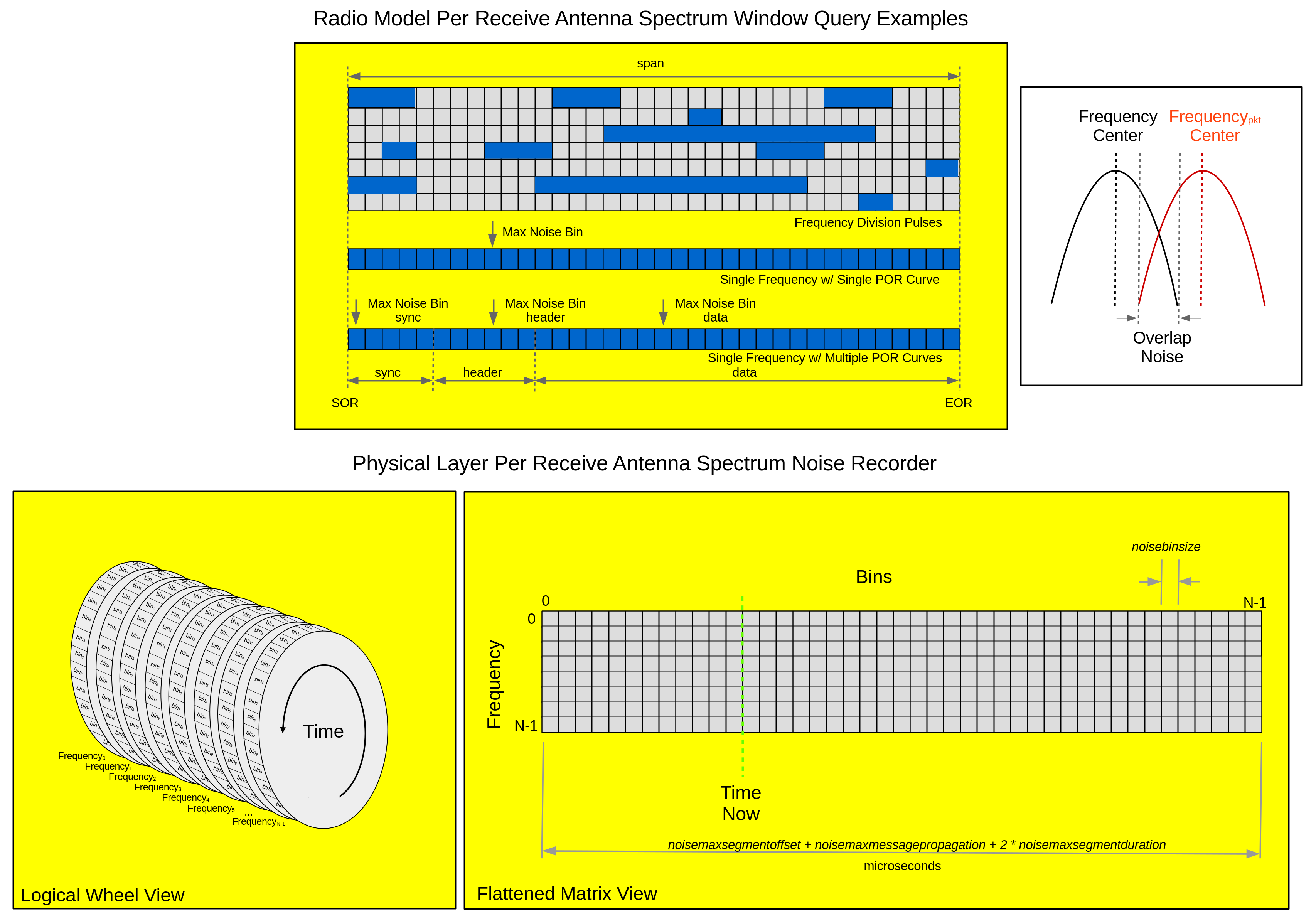
Energy recorders use a logical wheel of bins, where bin width in microseconds is set using the configuration parameter: noisebinsize. Each over-the-air transmission is checked for frequency overlap using the transmitter and receiver bandwidth. If there is any overlap, a proportional amount of signal energy is applied to each corresponding energy recorder wheel starting at the transmission start-of-reception:
$startOfReception = startOfTransmission + propagation + frequencySegmentOffset_0$
Where,
-
\(startOfTransmission\) is the start-of-transmission in microseconds contained in the Common Physical Layer Header:
txTimeMicroseconds. -
\(propagation\) is the propagation delay calculated when the location of the transmitting NEM and receiving NEM is known via
LocationEvents, or 0 when any respective location is unknown. -
\(frequencySegmentOffset_0\) is the offset in microseconds of the first frequency segment conveyed via the Common Physical Layer Header:
frequencyGroups[j].frequencySegments[0].offsetMicroseconds.
Physical layer configuration parameters: noisemaxsegmentduration, noisemaxmessagepropagation, and noisemaxsegmentoffset are used to set the maximum duration, propagation delay, and frequency segment offset, all in microseconds, respectively. By default, over-the-air transmissions containing values above the configured maximums will be dropped.
The physical layer has the ability to record all signal energy, out-of-band signal energy, or no signal energy determined by the configuration parameter noisemode value all, outofband, or none, respectively. When no signal energy is being recorded or no signal energy occurred over a given request interval, the receiver sensitivity is used as the noise floor.
When recording all signal energy, it is the radio model’s responsibility to remove the in-band signal from the spectrum window prior to computing the SINR.
The spectrum service can also be utilized by a radio model to support Dynamic Spectrum Access (DSA) by requesting a spectrum window over a valid time interval independent of an upstream over-the-air reception.
A radio model queries spectrum monitor energy using SpectrumServiceProvider::requestAntenna:
auto spectrumWindow =
  pRadioService_->spectrumService().requestAntenna(0, // antenna index
                                                   u64FrequencyHz,
                                                   span,
                                                   startOfReception);
Where, the returned spectrum window is a SpectrumWindow instance.
Frequency Diversity
The physical layer provides the ability to send multiple signals (of constant bandwidth) in frequency and/or time within a single over-the-air message. A compat1 radio model can utilize this feature by populating the FrequencyControlMessage which accompanies a downstream over-the-air message, with information for one or more frequency segments. Similarly, a compat2 radio model uses the MIMOTransmitPropertiesControlMessage to define one or more frequency groups, each of which containing information for one or more frequency segments, where each transmit antenna is associated with one of the defined frequency groups.
Frequency segment information includes the segment center frequency, total time duration, offset from the transmission time stamp and optionally, transmit power in dBm that overrides any overall transmitter power level.
Frequency information is included in the Common Physical Layer Header and divided into two parts, frequency group segments: frequencyGroups[j].frequencySegments[j].{frequencyHz, offsetMicroseconds, durationMicroseconds} and transmit antenna frequency group association and bandwidth: transmitAntennas[i].{frequencyGroupIndex, bandwidthHz}.
At the receiving NEM, depending on its noise mode, one of four actions will be taken for all segments where the \(rxPower > rxSensitivity\):
-
If
noisemodeisall, the signal energy for each frequency segment will be applied to the spectrum monitor based on frequency of interest bandwidth overlap. -
If
noisemodeisoutofbandand this is an out-of-band transmission, the signal energy for each frequency segment will be applied to the spectrum monitor based on frequency of interest bandwidth overlap. -
If
noisemodeisoutofbandand this is an in-band transmission, no energy will be applied to the spectrum monitor. -
If
noisemodeisnone, no energy will be applied to the spectrum monitor.
A radio model will only receive those frequency segments where $rxPower > rxSensitivity$. Any frequency segment that has a center frequency that is not in the physical layer’s frequency of interest list will cause the entire transmission to be treated as out-of-band.
Collaborative Transmission
The physical layer provides the ability to send a single over-the-air message specifying multiple transmitters to minimize over-the-air message processing during collaborative transmission. A radio model can utilize this feature by populating the TransmitterControlMessage, which accompanies a downstream over-the-air message, with information for multiple transmitters. Transmitter information includes the NEM id of the transmitter and the transmission power, and is included in the Common Physical Layer Header: transmitters[i].{nemId, powerdBm}.
It is the radio model’s responsibility to implement the coordination logic that allows one instance (NEM) to send the collaborative over-the-air transmission.
Upon the reception of an over-the-air message with multiple transmitters, the physical layer will calculate the \(rxPower\) from each transmitter and sum up the energy. Depending on the current noise mode, one of four actions will be taken, provided the \(\sum_{n=0}^{N} rxPower_n > rxSensitivity\), where \(N\) is the number of transmitters:
-
If
noisemodeisall, the summed energy will be applied to the spectrum monitor based on frequency of interest bandwidth overlap. -
If
noisemodeisoutofbandand this is an out-of-band message, the summed energy will be applied to the spectrum monitor based on frequency of interest bandwidth overlap. -
If
noisemodeisoutofbandand this is an in-band message, no energy will be applied to the spectrum monitor. -
If
noisemodeisnone, no energy will be applied to the spectrum monitor.
Regardless of noisemode, the radio model will only receive the over-the-air message when \(\sum_{n=0}^{N} rxPower_n > rxSensitivity\). The radio model will receive no indication that this message was a collaborative transmission.
Fading Model
The physical layer supports per source fading model selection that can be modified via FadingSelectionEvents. Fading selection is controlled by the fading.model configuration parameter and can be one of either none, event, nakagami, or lognormal. Specifying event requires using a FadingSelectionEvent in order to assign the fading model used at a receiving NEM for a specified NEM source.
The Nakagami-m Fading model uses a gamma distribution to determine a fade loss value based on distance and power. Configuration parameters provide the ability to model various fading effects experienced in both indoor and outdoor environments based on empirical data. Parameters are used to specify two distance thresholds: fading.nakagami.distance0 and fading.nakagami.distance1 (meters) in order to establish three distance bounds: below, between, and above; and three shape factors corresponding to the three distance bounds: fading.nakagami.m0, fading.nakagami.m1, and fading.nakagami.m2.
The Lognormal Fading model models Free Space Optical (FSO) loss using a statistical mechanism. The Lognormal Fading model works by creating a constant series of fades, each having a constant fade depth that may contribute to over-the-air loss. The fading model keeps track of the time each fading period ends and generates a new fading period upon the arrival of the next over-ther-air message after the conclusion of the current fading period. Fade depths are log normally distributed but constant during a given fading period. Fade lengths are normally distributed.
Lognormal Fading model configuration parameters are used to relate the fading depth to pathloss in order to cause a corresponding amount of over-the-air loss. There is an inverse relationship between fading depth and pathloss, where lower values for fading depth result in 100% loss, while higher values result in no loss. For values between no loss and full loss, linear interpolation is used to calculate the corresponding pathloss which may result in random loss during the fading period.
MIMO
The physical layer supports MIMO by allowing simultaneous use of multiple transmit and receive antenna. Waveform implementation specifics are modeled within the radio model, with control messages: MIMOTransmitPropertiesControlMessage and MIMOReceivePropertiesControlMessage conveying transmit and receive information between layers, respectively.
Using MIMO API control messages, a radio model can define any number of receive antenna (ideal omni or antenna profile defined), and similarly, add multiple transmit antenna to each over-the-air transmission. Every received over-the-air message will be processed once for each receive path, where the total number of receive paths is equal to the number of transmit antenna multiplied by the number of receive antenna.
Receive antennas are added using RxAntennaAddControlMessage, updated with RxAntennaUpdateControlMessage, and removed using RxAntennaRemoveControlMessage. When adding a receive antenna, a unique antenna index must be specified along with the frequency of interest information for the antenna and the antenna type: ideal omni (fixed gain) or antenna pattern defined (profile id and pointing). The unique index value supplied during RxAntennaAddControlMessage is how an antenna is referenced during an update or remove. It is also how per antenna receive power information is identified when communicating received over-the-air transmissions to the radio model via MIMOReceivePropertiesControlMessage.
When sending an over-the-air transmission, a radio model specifies one or more transmit antenna along with one or more groups of frequency segments using MIMOTransmitPropertiesControlMessage. Each transmit antenna may be mapped to its own unique group of frequency segments or share a group with other transmit antennas. Each transmit antenna is specified using a unique antenna index value which is unrelated to indexes used when adding receive antennas via RxAntennaAddControlMessage.
A radio model is free to use the same index for receive and transmit antennas to create its own logical association of the same antenna being used for both receive and transmit. The physical layer does not store any transmit antenna information in the downstream direction. In the upstream (receive) direction, the physical layer caches computed gain information when using antenna profiles, so it is important to be consistent when indexing transmit antennas when sending over-the-air transmissions. For example, if NEM 1 has antenna A1 and antenna A2, where A1 is pointing at (Az1,El1) and A2 is pointing at (Az2,El2), sending over-the-air transmissions and alternating or changing transmit antenna indexes while not updating position and/or pointing, will defeat any possible receive side caching gains which are keyed off of transmit antenna index. Pick indexes for A1 and A2, then be consistent so receiving physical layers do not invalidate cached antenna gains unless actual position and/or pointing updates dictate so.
Creating Antennas
When using RxAntennaAddControlMessage to add receive antenna, one of the following methods to create antenna instances should be used:
-
Antenna::createDefault(): Creates a default antenna which will either be an ideal omni with a fixed gain or a profile defined antenna, based on the physical layerfixedantennagainenableconfiguration parameter – compat1 mechanism for using the default antenna. -
Antenna::createIdealOmni(): Creates an ideal omni antenna with a specified fixed gain. -
Antenna::createProfileDefined(): Creates an antenna profile defined antenna with an optional initial pointing.
If the newly created receive antenna does not have it’s bandwidth set, the physical layer will use the value from its bandwidth configuration parameter.
If the RxAntennaAddControlMessage contains an empty frequency of interest set, the physical layer will use the value(s) from its frequencyofinterest configuration parameter.
When sending a MIMOTransmitPropertiesControlMessage, use one of the following methods to create the transmit antenna:
-
Antenna::createIdealOmni(): Creates an ideal omni antenna with a specified fixed gain. -
Antenna::createProfileDefined(): Creates an antenna profile defined antenna with an optional initial pointing.
Use an empty antenna set when creating a MIMOTransmitPropertiesControlMessage to indicate use of the default antenna configuration, which follows the same assignment logic as Antenna::createDefault().
If the newly created antenna does not have it’s bandwidth set, the physical layer will use the value from its bandwidth configuration parameter.
If any frequency segment has a 0 Hz specified frequency, the physical layer will use the value from its frequency configuration parameter.
If any frequency segment does not specify a transmit power, the physical layer will use the value from its txpower configuration parameter.
Antenna Profiles and Pointing
MIMO API radio models (compat2) using antenna profiles must specify pointing information in every over-the-air transmission as part of MIMOTransmitPropertiesControlMessage. The MIMO compatible physical layer supports event compatibility with compat1 radio models using external AntennaProfileEvent events. Where, the AntennaProfileEvent allows for specifying profile and pointing information for a single antenna (always index 0) for each specified NEM.
When using the MIMO API to point and transmit simultaneously, and modeling a logical re-pointing of the same antenna for receive, you must specify both a MIMOTransmitPropertiesControlMessage and a RxAntennaUpdateControlMessage in order for the pointing to take effect for receive.
Doppler
The physical layer calculates and applies Doppler shift when transmitter and receiver location and velocity are known at the receiver, and the dopplershiftenable configuration parameter is set to on. Doppler shift is applied when energy is added to spectrum monitor bins based on bandwidth overlap. Doppler shift information is communicated to compat2 radio models via the MIMOReceivePropertiesControlMessage as a mapping of center frequencies and their corresponding shift, both in Hz.
Spectral Masks
The physical layer provides support for using spectral masks to model the effects of transmitters that radiate energy at frequencies (side lobes and spurs) outside their defined bandwidth (main lobe/beam). A spectral mask manifest defines one or more spectral masks, where the spectral mask manifest is defined using the emulator configuration parameter: spectralmaskmanifesturi.
If spectral masks are being used by one or more NEMs within the emulation, the spectralmaskmanifesturi configuration parameter must be configured for all emulator instances, including those instances with an NEM not transmitting with a spectral mask. This is necessary for a receiving NEM to determine the txPower when performing the receive power calculation.
A spectral mask is composed of a primary signal and zero or more spurs. Each spectral mask must have a unique non-zero id.
<spectral-mask-manifest>
  <mask id='1'>
    <primary>
      <width hz='1M' dBr='0'/>
    </primary>
  </mask>
  <mask id='2'>
    <primary>
      <width hz='500K' dBr='-60'/>
      <width hz='500K' dBr='-30'/>
      <width hz='1M' dBr='0'/>
      <width hz='500K' dBr='-30'/>
      <width hz='500K' dBr='-60'/>
    </primary>
  </mask>
  <mask id='3'>
    <primary>
      <width hz='500K' dBr='-60'/>
      <width hz='500K' dBr='-30'/>
      <width hz='1M' dBr='0'/>
      <width hz='500K' dBr='-30'/>
      <width hz='500K' dBr='-60'/>
     </primary>
     <spurs>
      <spur offset_from_center_hz='1G'>
        <width hz='10K' dBr='10'/>
      </spur>
     </spurs>
  </mask>
</spectral-mask-manifest>
-
Both
<primary>and<spur>elements are defined using one or more contiguous segments specified in length (Hz) and a reference power offset (dBr) to be applied to the received signal relative to receiver bandwidth overlap. -
<spur>elements contain an offset from the center transmit frequency in Hz.
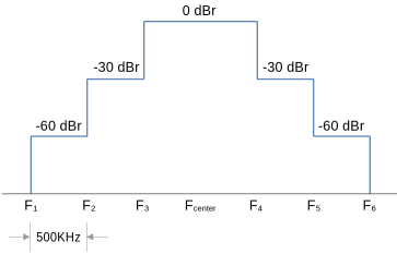
Visualization of mask id 2 shown above.
By default, the physical layer uses a square mask across the entire transmit bandwidth. When using spectral masks, the transmit bandwidth is determined at the receiver to be the total width defined by the respective mask element segments.
Compat1 and compat2 radio models can use the physical layer configuration parameter spectralmaskindex to set the spectral mask in use when transmitting. Compat2 radio models can dynamically set the transmit antenna spectral mask MIMOTransmitPropertiesControlMessage. Transmit antenna spectral mask index is contained in the Common Physical Layer Header: transmitAntennas[i].spectralMaskIndex
Spectrum Filters
The physical layer provides a radio model with the ability to specify one or more spectrum filters which record spectrum energy based on a set of specified criteria. Filter spectrum windows are queried similar to spectrum energy windows, and are used in conjunction with spectrum energy windows to perform actions such as excision and cancellation.
A radio model adds one or more spectrum filters using SpectrumFilterAddControlMessage within a downstream control message:
sendDownstreamControl({SpectrumFilterAddControlMessage::create(1, // unique filter index
                                                               0, // antenna index
                                                               1000000000, // center freq
                                                               20000000, // bandwidth
                                                               100000, // sub-band width in hz
                                                               BandwidthFilterElementLessEqual::create(100000)
                                                               )});
Spectrum filters are added per receive antenna using a unique filter index for a given center frequency (Hz) and bandwidth (hz), along with an optional sub-band width (Hz) length that subdivides spectral energy into sub-band width bins of specified size for each time bin in the filter energy window. Additionally, optional match criteria can be supplied to allow for more precise control of which energy is captured.
A radio model removes one or more spectrum filters using SpectrumFilterRemoveControlMessage within a downstream control message:
sendDownstreamControl({SpectrumFilterRemoveControlMessage::create(1, // unique filter index
                                                                  0)}); // antenna index
By default, filters do not record energy with the same subid as their associated physical layer (in-band waveform). Set the physical layer confiugration parameter excludesamesubidfromfilterenable to false to allow filter processing of in-band spectrum energy and add SubIdFilterElementEqual::create(0) to the FilterMatchCriterion expression. Where, subid 0 means match the radio model’s associated physical layer subid.
Match criteria may be specified using any combination of the following:
FrequencyFilterElementLessFrequencyFilterElementLessEqualFrequencyFilterElementGreaterFrequencyFilterElementGreaterEqualFrequencyFilterElementEqualFrequencyFilterElementNotEqualBandwidthFilterElementLessBandwidthFilterElementLessEqualBandwidthFilterElementGreaterBandwidthFilterElementGreaterEqualBandwidthFilterElementEqualBandwidthFilterElementNotEqualSubIdFilterElementLessSubIdFilterElementLessEqualSubIdFilterElementGreaterSubIdFilterElementGreaterEqualSubIdFilterElementEqualSubIdFilterElementNotEqualSubIdFilterElementLessSubIdFilterElementLessEqualSubIdFilterElementGreaterSubIdFilterElementGreaterEqualSubIdFilterElementEqualSubIdFilterElementNotEqualFilterDataFilterElementEqualFilterDataFilterElementNotEqual
More complex compound expressions are created using:
Filter data is opaque data a radio model can attach to a downstream over-the-air transmission to allow additional match criteria. This opaque data can be used in conjunction with a custom FilterMatchCriterion expression, or with FilterDataFilterElementEqual or FilterDataFilterElementNotEqual.
SpectrumFilterAddControlMessage::create(2, // Filter Index
                                        2347000000, // Freq 1GHz
                                        20000000, // 20 MHz bandwidth
                                        0, // no sub-bands
                                        FilterDataFilterElementEqual::create("Hello World!"));
A radio model uses the SpectrumFilterDataControlMessage to add filter data when sending a downstream packet:
sendDownstreamPacket(CommonMACHeader{type_, u16SequenceNumber_++},
                   pkt,
                   {Controls::SpectrumFilterDataControlMessage::create("Hello World!"),
                    ...
                   })
A radio model queries spectrum filter energy using SpectrumServiceProvider::requestAntennaFilter:
auto windowFilter =
  pRadioService_->spectrumService().requestAntennaFilter(0, // antenna index
                                                         1, // unique filter index
                                                         span,
                                                         startOfReception);
Where, the returned filter window is a SpectrumFilterWindow instance. In this example, the filter was added with a sub-band width causing the energy values contained in the spectrum window to be:
[T_0_SUB_0,TO_SUB_1,...,TO_SUB_N,T1_SUB_0,T1_SUB_1,...,T1_SUB_N,...]
The number of sub-band entries per time bin (N) is returned as the last item in the windowFilter tuple:
auto subBandBinCount = std::get<4>(windowFilter);
Platform Orientation
The physical layer accounts for the transmitting and receiving NEM’s platform orientation when determining the antenna gain based on antenna profiles.
Location Events are required when using antenna profiles and each event includes the following 3 elements for a given NEM:
-
position - latitude, longitude, altitude (required)
-
velocity - azimuth, elevation, magnitude (optional, defaults to 0)
-
orientation - pitch, roll, yaw (optional, defaults to 0)
The position element identifies the platform’s location and not the antenna location, as a given platform may have more than one antenna. In cases where a platform has multiple antenna and their location on the platform needs to be accounted for, the <placement> element within the antenna manifest is utilized to define the offset of each antenna relative to the platform’s position. The velocity element identifies the speed and direction of the platform relative to true north.
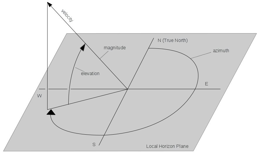
Orientation defines the pitch, roll and yaw angles (Euler angels) about the platform’s latitudinal, longitudinal and vertical axes respectively. Yaw and pitch are defined relative to the velocity vector’s azimuth and elevation components respectively and roll is defined relative to wings level position.
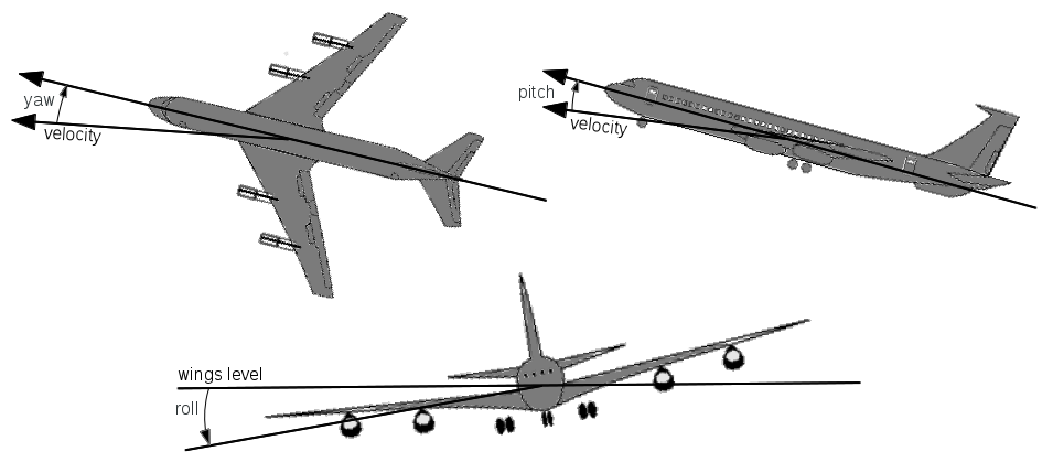
The arrow directions indicate positive angles.
Configuration
-
bandwidth: Defines receiver bandwidth in Hz and also serves as the default bandwidth for OTA transmissions when not provided by the MAC.Default: yes Required: no Modifiable: no Type: uint64 Occurrs: [1,1] Range: [1,max_uint64] Values: 1000000 -
compatibilitymode: Defines the physical layer compatibility mode.Default: yes Required: no Modifiable: no Type: uint16 Occurrs: [1,1] Range: [1,2] Values: 1 -
dopplershiftenable: Defines whether to perform Doppler shift processing when location and velocity information is known for both the transmitter and receiver.Default: yes Required: no Modifiable: no Type: bool Occurrs: [1,1] Range: [false,true] Values: true -
excludesamesubidfromfilterenable: Defines whether over-the- air (downstream) messages with a subid matching the emulator PHY subid (inband) should be processed for filter inclusion.Default: yes Required: no Modifiable: no Type: bool Occurrs: [1,1] Range: [false,true] Values: true -
fading.lognormal.dlthresh: Defines the lognormal fading depth lower threshold (below this threshold is 0% POR/100% loss).Default: yes Required: no Modifiable: yes Type: double Occurrs: [1,1] Range: [min_double,max_double] Values: 0.250000 -
fading.lognormal.dmu: Defines the lognormal fading depth mu (mean of underlying normal distribution).Default: yes Required: no Modifiable: yes Type: double Occurrs: [1,1] Range: [min_double,max_double] Values: 5.000000 -
fading.lognormal.dsigma: Defines the lognormal fading depth sigma (standard deviation of underlying normal distribution).Default: yes Required: no Modifiable: yes Type: double Occurrs: [1,1] Range: [min_double,max_double] Values: 1.000000 -
fading.lognormal.duthresh: Defines the lognormal fading depth upper threshold (above this threshold is 100% POR/0% loss).Default: yes Required: no Modifiable: yes Type: double Occurrs: [1,1] Range: [min_double,max_double] Values: 0.750000 -
fading.lognormal.lmean: Defines the lognormal fading length mean in seconds (normal distribution).Default: yes Required: no Modifiable: yes Type: double Occurrs: [1,1] Range: [0.000000,max_double] Values: 0.005000 -
fading.lognormal.lstddev: Defines the lognormal fading length standard deviation in seconds (normal distribution).Default: yes Required: no Modifiable: yes Type: double Occurrs: [1,1] Range: [0.000000,max_double] Values: 0.001000 -
fading.lognormal.maxpathloss: Defines the pathloss value (in dBm) corresponding to the fading depth lower threshold (0% POR/100% loss).Default: yes Required: no Modifiable: yes Type: double Occurrs: [1,1] Range: [min_double,max_double] Values: 100.000000 -
fading.lognormal.minpathloss: Defines the pathloss value (in dBm) corresponding to the fading depth upper threshold (100% POR/0% loss).Default: yes Required: no Modifiable: yes Type: double Occurrs: [1,1] Range: [min_double,max_double] Values: 0.000000 -
fading.model: Defines the fading model: none, event, lognormal, nakagami.Default: yes Required: no Modifiable: yes Type: string Occurrs: [1,1] Regex: ^(none|event|lognormal|nakagami)$ Values: none -
fading.nakagami.distance0: Defines the distance in meters used for lower bound shape selection.Default: yes Required: no Modifiable: yes Type: double Occurrs: [1,1] Range: [min_double,max_double] Values: 100.000000 -
fading.nakagami.distance1: Defines the distance in meters used for upper bound shape selection.Default: yes Required: no Modifiable: yes Type: double Occurrs: [1,1] Range: [min_double,max_double] Values: 250.000000 -
fading.nakagami.m0: Defines the shape factor to use for distance < fading.nakagami.distance0.Default: yes Required: no Modifiable: yes Type: double Occurrs: [1,1] Range: [0.500000,max_double] Values: 0.750000 -
fading.nakagami.m1: Defines the shape factor to use for distance >= fading.nakagami.distance0 and < fading.nakagami.distance1.Default: yes Required: no Modifiable: yes Type: double Occurrs: [1,1] Range: [0.500000,max_double] Values: 1.000000 -
fading.nakagami.m2: Defines the shape factor to use for distance >= fading.nakagami.distance1.Default: yes Required: no Modifiable: yes Type: double Occurrs: [1,1] Range: [0.500000,max_double] Values: 200.000000 -
fixedantennagain: Defines the antenna gain in dBi and is valid only when fixedantennagainenable is enabled.Default: yes Required: no Modifiable: yes Type: double Occurrs: [1,1] Range: [min_double,max_double] Values: 0.000000 -
fixedantennagainenable: Defines whether fixed antenna gain is used or whether antenna profiles are in use.Default: yes Required: no Modifiable: no Type: bool Occurrs: [1,1] Range: [false,true] Values: true -
frequency: Defines the default transmit center frequency in Hz when not provided by the MAC. This value is included in the Common PHY Header of all transmitted OTA packets.Default: yes Required: no Modifiable: no Type: uint64 Occurrs: [1,1] Range: [1,max_uint64] Values: 2347000000 -
frequencyofinterest: Defines a set of center frequencies in Hz that are monitored for reception as either in-band or out-of-band.Default: yes Required: no Modifiable: no Type: uint64 Occurrs: [1,max_uint64] Range: [0,max_uint64] Values: 2347000000 -
noisebinsize: Defines the noise bin size in microseconds and translates into timing accuracy associated with aligning the start and end of reception times of multiple packets for modeling of interference effects.Default: yes Required: no Modifiable: no Type: uint64 Occurrs: [1,1] Range: [1,max_uint64] Values: 20 -
noisemaxclampenable: Defines whether segment offset, segment duration and message propagation associated with a received packet will be clamped to their respective maximums defined by noisemaxsegmentoffset, noisemaxsegmentduration and noisemaxmessagepropagation. When disabled, any packet with an above max value will be dropped.Default: yes Required: no Modifiable: no Type: bool Occurrs: [1,1] Range: [false,true] Values: false -
noisemaxmessagepropagation: Noise maximum message propagation in microseconds.Default: yes Required: no Modifiable: no Type: uint64 Occurrs: [1,1] Range: [1,max_uint64] Values: 200000 -
noisemaxsegmentduration: Noise maximum segment duration in microseconds.Default: yes Required: no Modifiable: no Type: uint64 Occurrs: [1,1] Range: [1,max_uint64] Values: 1000000 -
noisemaxsegmentoffset: Noise maximum segment offset in microseconds.Default: yes Required: no Modifiable: no Type: uint64 Occurrs: [1,1] Range: [1,max_uint64] Values: 300000 -
noisemode: Defines the noise processing mode of operation: none, all, outofband or passthrough.Default: yes Required: no Modifiable: no Type: string Occurrs: [1,1] Regex: ^(none|all|outofband|passthrough)$ Values: all -
processingpoolsize: Defines the number of processing pool threads. If > 2, pool threads are used to process receive paths per receive antenna. Using a processing pool does not guarantee increased performance. The processing pool can reduce the amount of processing time for an upstream message that contains a large number of frequency segments and/or a large number of transmit antenna (MIMO). Without a processing pool, receive paths are calculated serially in a loop. There is a threshold where serial processing is faster than the context switching of the thread pool. Additionally, if the number of cores available to a running emane process is less than the processing pool size, worse performance may be encountered.Default: yes Required: no Modifiable: no Type: uint16 Occurrs: [1,1] Range: [0,65535] Values: 0 -
propagationmodel: Defines the pathloss mode of operation: precomputed, 2ray or freespace.Default: yes Required: no Modifiable: no Type: string Occurrs: [1,1] Regex: ^(precomputed|2ray|freespace)$ Values: precomputed -
radiosilenceenable: Defines whether transmission is allowed. When enabledover-the-air (downstream) messages will be dropped.Default: yes Required: no Modifiable: yes Type: bool Occurrs: [1,1] Range: [false,true] Values: false -
rxsensitivitypromiscuousmodeenable: Defines whether over- the-air messages are sent upstream if below receiver sensitivity. Compatibility mode > 1 only. Messages sent upstream without a MIMOReceivePropertiesControlMessage.Default: yes Required: no Modifiable: no Type: bool Occurrs: [1,1] Range: [false,true] Values: false -
spectralmaskindex: Defines the spectral mask index used for all transmissions. Set to 0 to use the emulator default square spectral mask.Default: yes Required: no Modifiable: no Type: uint16 Occurrs: [1,1] Range: [0,65535] Values: 0 -
stats.observedpowertableenable: Defines whether the observed power table will be populated. Large number of antenna (MIMO) and/or frequency segments will increase processing load when populating.Default: yes Required: no Modifiable: no Type: bool Occurrs: [1,1] Range: [false,true] Values: true -
stats.receivepowertableenable: Defines whether the receive power table will be populated. Large number of antenna (MIMO) and/or frequency segments will increase processing load when populating.Default: yes Required: no Modifiable: no Type: bool Occurrs: [1,1] Range: [false,true] Values: true -
subid: Defines the emulator PHY subid used by multiple NEM definitions. Once instantiated, these NEMs may be using the same frequency. In order to differentiate between emulator PHY instances for different waveforms, the subid is used as part of the unique waveform identifying tuple: PHY Layer Registration Id, emulator PHY subid and packet center frequency.Default: no Required: yes Modifiable: no Type: uint16 Occurrs: [1,1] Range: [1,65535] -
systemnoisefigure: Defines the system noise figure in dB and is used to determine the receiver sensitivity.Default: yes Required: no Modifiable: no Type: double Occurrs: [1,1] Range: [min_double,max_double] Values: 4.000000 -
timesyncthreshold: Defines the time sync detection threshold in microseconds. If a received OTA message is more than this threshold, the message reception time will be used as the source transmission time instead of the time contained in the Common PHY Header. This allows the emulator to be used across distributed nodes without time sync.Default: yes Required: no Modifiable: no Type: uint64 Occurrs: [1,1] Range: [1,max_uint64] Values: 10000 -
txpower: Defines the transmit power in dBm.Default: yes Required: no Modifiable: yes Type: double Occurrs: [1,1] Range: [min_double,max_double] Values: 0.000000
Statistics
-
avgDownstreamProcessingDelay0: Average downstream processing delayType: float Clearable: yes -
avgDownstreamQueueDelay:Type: float Clearable: yes -
avgProcessAPIQueueDepth: Average API queue depth for a processUpstreamPacket, processUpstreamControl, processDownstreamPacket, processDownstreamControl, processEvent and processTimedEvent.Type: double Clearable: yes -
avgProcessAPIQueueWait: Average API queue wait for a processUpstreamPacket, processUpstreamControl, processDownstreamPacket, processDownstreamControl, processEvent and processTimedEvent in microseconds.Type: double Clearable: yes -
avgTimedEventLatency: Average latency between the scheduled timer expiration and the actual firing over the requested duration.Type: double Clearable: yes -
avgTimedEventLatencyRatio: Average ratio of the delta between the scheduled timer expiration and the actual firing over the requested duration. An average ratio approaching 1 indicates that timer latencies are large in comparison to the requested durations.Type: double Clearable: yes -
avgUpstreamProcessingDelay0: Average upstream processing delayType: float Clearable: yes -
numAPIQueued: The number of queued API events.Type: uint64 Clearable: yes -
numDownstreamBytesBroadcastGenerated0: Number of layer generated downstream broadcast bytesType: uint64 Clearable: yes -
numDownstreamBytesBroadcastRx0: Number of downstream broadcast bytes receivedType: uint64 Clearable: yes -
numDownstreamBytesBroadcastTx0: Number of downstream broadcast bytes transmittedType: uint64 Clearable: yes -
numDownstreamBytesUnicastGenerated0: Number of layer generated downstream unicast bytesType: uint64 Clearable: yes -
numDownstreamBytesUnicastRx0: Number of downstream unicast bytes receivedType: uint64 Clearable: yes -
numDownstreamBytesUnicastTx0: Number of downstream unicast bytes transmittedType: uint64 Clearable: yes -
numDownstreamPacketsBroadcastDrop0: Number of downstream broadcast packets droppedType: uint64 Clearable: yes -
numDownstreamPacketsBroadcastGenerated0: Number of layer generated downstream broadcast packetsType: uint64 Clearable: yes -
numDownstreamPacketsBroadcastRx0: Number of downstream broadcast packets receivedType: uint64 Clearable: yes -
numDownstreamPacketsBroadcastTx0: Number of downstream broadcast packets transmittedType: uint64 Clearable: yes -
numDownstreamPacketsUnicastDrop0: Number of downstream unicast packets droppedType: uint64 Clearable: yes -
numDownstreamPacketsUnicastGenerated0: Number of layer generated downstream unicast packetsType: uint64 Clearable: yes -
numDownstreamPacketsUnicastRx0: Number of downstream unicast packets receivedType: uint64 Clearable: yes -
numDownstreamPacketsUnicastTx0: Number of downstream unicast packets transmittedType: uint64 Clearable: yes -
numDownstreamQueueDelay: Accumulation of downstream queue delay in microseconds.Type: uint64 Clearable: yes -
numHighWaterMark: Downstream queue high water mark in packets.Type: uint32 Clearable: yes -
numUpstreamBytesBroadcastRx0: Number of upstream broadcast bytes receivedType: uint64 Clearable: yes -
numUpstreamBytesBroadcastTx0: Number of updtream broadcast bytes transmittedType: uint64 Clearable: yes -
numUpstreamBytesUnicastRx0: Number upstream unicast bytes receivedType: uint64 Clearable: yes -
numUpstreamBytesUnicastTx0: Number of upstream unicast bytes transmittedType: uint64 Clearable: yes -
numUpstreamPacketsBroadcastDrop0: Number of upstream broadcast packets droppedType: uint64 Clearable: yes -
numUpstreamPacketsBroadcastRx0: Number of upstream broadcast packets receivedType: uint64 Clearable: yes -
numUpstreamPacketsBroadcastTx0: Number of upstream broadcast packets transmittedType: uint64 Clearable: yes -
numUpstreamPacketsUnicastDrop0: Number of upstream unicast packets droppedType: uint64 Clearable: yes -
numUpstreamPacketsUnicastRx0: Number upstream unicast packets receivedType: uint64 Clearable: yes -
numUpstreamPacketsUnicastTx0: Number of upstream unicast packets transmittedType: uint64 Clearable: yes -
processedConfiguration: The number of processed configuration.Type: uint64 Clearable: yes -
processedDownstreamControl: The number of processed downstream control.Type: uint64 Clearable: yes -
processedDownstreamPackets: The number of processed downstream packets.Type: uint64 Clearable: yes -
processedEvents: The number of processed events.Type: uint64 Clearable: yes -
processedTimedEvents: The number of processed timed events.Type: uint64 Clearable: yes -
processedUpstreamControl: The number of processed upstream control.Type: uint64 Clearable: yes -
processedUpstreamPackets: The number of processed upstream packets.Type: uint64 Clearable: yes
Statistic Tables
-
BroadcastPacketAcceptTable0: Broadcast packets acceptedClearable: yes -
BroadcastPacketDropTable0: Broadcast packets dropped by reason codeClearable: yes -
EventReceptionTable: Received event countsClearable: yes -
NeighborMetricTable: Neighbor Metric TableClearable: no -
NeighborStatusTable: Neighbor Status TableClearable: no -
RFSignalTable: Rf Signal TableClearable: no -
UnicastPacketAcceptTable0: Unicast packets acceptedClearable: yes -
UnicastPacketDropTable0: Unicast packets dropped by reason codeClearable: yes