Bent Pipe Radio Model
The Bent Pipe radio model is a generic regenerative bent-pipe (u-bend) satellite model. The model supports configuration of one or more transponders, where each transponder may operate in ubend or process mode. A transponder operating in ubend mode will relay any successfully received over-the-air uplink frame over its downlink channel. A transponder operating in process mode will forward any successfully received over-the-air frame up the stack for processing. Bent Pipe differentiates between operating as a satellite or ground station solely based on transponder configuration, specifically the configuration parameter transponder.receive.action either set to ubend or process, and can be configured as a satellite with inter-satellite links by using a combination of ubend and process transponders.
Features
The Bent Pipe radio model provides the following set of features: Multiple Transponders, Configurable Channel Access, Multiple Antenna, Aggregation and Fragmentation, Boundary Transponder Selection, and Packet Completion Rate Curves.
Multiple Transponders
The Bent Pipe radio model can be configured with multiple transponders where each is configured using a set of configuration parameters with a <transponder index>:<value> format. Where <transponder index> is a 0 based sequential index used to identify the transponders instantiated by the model.
Each transponder needs both receive and transmit configuration and must be included as an entry in each of the transponder.receiver.* and transponder.transmit.* configuration parameter values.
Failure to include a referenced transponder in any of the required configuration, using non-sequential transponder indices, or mixing na and non-na values for the same transponder in transponder.transmit.* TDMA channel access parameters, will result in a configuration exception at emulator start.
The below radio model XML snippet from node-1 in the bentpipe-01 example shows transponder.receiver.* configuration for a Bent Pipe model configured with a single transponder in process mode.
  <!-- syntax: '<transponder id>:<rx freqeuncy Hz>' -->
  <paramlist name='transponder.receive.frequency'>
    <item value='0:29.910G'/>
  </paramlist>

  <!-- syntax: '<transponder id>:<rx bandwidth Hz>' -->
  <paramlist name='transponder.receive.bandwidth'>
    <item value='0:150M'/>
  </paramlist>

  <!-- syntax: '<transponder id>:<rx action: ubend | process>' -->
  <paramlist name='transponder.receive.action'>
    <item value='0:process'/>
  </paramlist>

  <!-- syntax: '<transponder id>:<pcr index>' -->
  <paramlist name='transponder.transmit.pcrcurveindex'>
    <item value='0:0'/>
  </paramlist>

 <!-- syntax: '<transponder id>:<antenna index>' -->
  <paramlist name='transponder.receive.antenna'>
    <item value='0:0'/>
  </paramlist>

  <!-- syntax: '<transponder id>:<on | off>' -->
  <paramlist name='transponder.receive.enable'>
    <item value='0:on'/>
  </paramlist>
emane-guide/examples/bentpipe-01/node-1/emane-bentpipe-radiomodel.xml lines: 7-36
Comparing the above snippet with the following from node-2 in the bentpipe-02 example, highlights the transponder.receiver.* similarities and differences when configuring multiple transponders and operating in ubend mode – mainly the number of <paramlist> items with unique transponder indices.
  <!-- syntax: '<transponder id>:<rx freqeuncy Hz>' -->
  <paramlist name='transponder.receive.frequency'>
    <item value='0:29.910G'/>
    <item value='1:29.745G'/>
    <item value='2:29.580G'/>
  </paramlist>

  <!-- syntax: '<transponder id>:<rx bandwidth Hz>' -->
  <paramlist name='transponder.receive.bandwidth'>
    <item value='0:150M'/>
    <item value='1:150M'/>
    <item value='2:150M'/>
  </paramlist>

  <!-- syntax: '<transponder id>:<rx action: ubend | process>' -->
  <paramlist name='transponder.receive.action'>
    <item value='0:ubend'/>
    <item value='1:ubend'/>
    <item value='2:ubend'/>
  </paramlist>

  <!-- syntax: '<transponder id>:<pcr index>' -->
  <paramlist name='transponder.transmit.pcrcurveindex'>
    <item value='0:0'/>
    <item value='1:0'/>
    <item value='2:0'/>
  </paramlist>

 <!-- syntax: '<transponder id>:<antenna index>' -->
  <paramlist name='transponder.receive.antenna'>
    <item value='0:0'/>
    <item value='1:1'/>
    <item value='2:2'/>
  </paramlist>

  <!-- syntax: '<transponder id>:<on | off>' -->
  <paramlist name='transponder.receive.enable'>
    <item value='0:on'/>
    <item value='1:on'/>
    <item value='2:on'/>
  </paramlist>
emane-guide/examples/bentpipe-02/node-2/emane-bentpipe-radiomodel.xml lines: 7-48
Configurable Channel Access
A transponder can be configured to use either TDMA or No-Protocol (no channel access) channel access when transmitting. Specifying a non-na value for transponder.transmit.slotsize, transponder.transmit.slotperframe, and transponder.transmit.txslots configuration parameters selects TDMA channel access. Transponders instantiated by a Bent Pipe instance may have different slot and frame sizes, and different tx slot allocations.
The following snippet from node-1 in the bentpipe-02 example illustrates the configuration necessary for a TDMA transmit channel with 10 1000 msec slots per frame and the assigning of individual transmit slots to node-1.
  <!-- syntax: '<transponder id>:<tx slots | na>' -->
  <paramlist name='transponder.transmit.txslots'>
    <item value='0:1;3;5;7;9'/>
  </paramlist>

  <!-- syntax: '<transponder id>:<tx slot size | na>' -->
  <paramlist name='transponder.transmit.slotsize'>
    <item value='0:1000'/>
  </paramlist>

  <!-- syntax: '<transponder id>:<tx slot per frame | na>' -->
  <paramlist name='transponder.transmit.slotperframe'>
    <item value='0:10'/>
  </paramlist>
emane-guide/examples/bentpipe-02/node-1/emane-bentpipe-radiomodel.xml lines: 57-71
Specifying those same configuration parameters as na, as does node-3 in the bentpipe-02 example, selects no-protocol channel access, which is functionally equivalent to the RF Pipe Model.
  <!-- syntax: '<transponder id>:<tx slots | na>' -->
  <paramlist name='transponder.transmit.txslots'>
    <item value='0:na'/>
  </paramlist>

  <!-- syntax: '<transponder id>:<tx slot size | na>' -->
  <paramlist name='transponder.transmit.slotsize'>
    <item value='0:na'/>
  </paramlist>

  <!-- syntax: '<transponder id>:<tx slot per frame | na>' -->
  <paramlist name='transponder.transmit.slotperframe'>
    <item value='0:na'/>
  </paramlist>
emane-guide/examples/bentpipe-02/node-3/emane-bentpipe-radiomodel.xml lines: 57-71
Multiple Antenna
The Bent Pipe radio model can be configured with multiple antennas using the configuration parameter antenna.defines. Each antenna is defined as a parameter value entry using the format <antenna index>:<antenna definition>. Where <antenna index> is a 0 based unique index used to identify a specific antenna.
Ideal omni antennas are defined using the following format:
<antenna index>:omni;<fixed antenna gain dbi>;<spectral mask index>
Profile defined antennas are defined using the following format:
<antenna index>:<antenna profile>;<azimuth degrees>;<elevation degrees>;<spectral mask index>
Below is the antenna definition used by the node-2 in the bentpipe-02 example showing the definition for three profile defined antennas:
  <paramlist name='antenna.defines'>
    <item value='0:2;0;0;0'/>
    <item value='1:1;94.34439424144891;-86.98230090133954;0'/>
    <item value='2:1;237.5217814216051;-87.42647720511944;0'/>
  </paramlist>
emane-guide/examples/bentpipe-02/node-2/emane-bentpipe-radiomodel.xml lines: 131-135
A transponder must be associated with a receive and transmit antenna, which may be the same, using the configuration parameters transponder.receive.antenna and transponder.transmit.antenna, respectively. An antenna is identified by the antenna index used in antenna.defines.
Below is the transponder receive and transmit antenna mappings for node-2 in the bentpipe-02 example.
  <paramlist name='transponder.receive.antenna'>
    <item value='0:0'/>
    <item value='1:1'/>
    <item value='2:2'/>
  </paramlist>
emane-guide/examples/bentpipe-02/node-2/emane-bentpipe-radiomodel.xml lines: 36-41
  <paramlist name='transponder.transmit.antenna'>
    <item value='0:0'/>
    <item value='1:2'/>
    <item value='2:1'/>
  </paramlist>
emane-guide/examples/bentpipe-02/node-2/emane-bentpipe-radiomodel.xml lines: 99-104
Aggregation and Fragmentation
The Bent Pipe radio model can be configured to aggregate small over-the-air messages up to a certain maximum transmission unit (MTU) and/or fragment ones larger than the same MTU. Aggregation is enabled using the configuration parameter queue.aggregationenable. Fragmentation is enabled using the configuration parameter queue.fragmentationenable.
MTU definition is transponder specific. When using TDMA channel access, the MTU is calculated using the transponder.transmit.slotsize and transponder.transmit.datarate configuration parameters. When using no-protocol channel access the MTU is specified using the configuration parameter transponder.transmit.mtu.
Boundary Transponder Selection
When using process mode, downstream messages that are communicated to the Bent Pipe model for over-the-air transmission use a TOS or DSCP mapping to transponder index in order to direct over-the-air messages, depending on what is provided by the boundary component in use. Both the Raw Transport and Virtual Transport use DSCP.
The below configuration from node-1 in the bentpipe-01 example directs all downstream over-the-air messages to transponder 0.
  <paramlist name='transponder.transmit.tosmap'>
     <item value='0:0-255'/>
  </paramlist>
emane-guide/examples/bentpipe-01/node-1/emane-bentpipe-radiomodel.xml lines: 87-89
Packet Completion Rate Curves
The Bent Pipe radio model Packet Completion Rate is specified as curves defined via XML. The curve definitions are composed of a series of SINR values along with their corresponding probability of reception for a given index which is assigned to a transponder using the configuration parameter transponder.transmit.pcrcurveindex.
A curve definition must contain a minimum of two points with one SINR representing POR = 0 and one SINR representing POR = 100. Linear interpolation is preformed when an exact SINR match is not found.
Specifying a packet size (<bentpipe-model-pcr> attribute packetsize) in the curve file will adjust the POR based on received packet size. Specifying a packetsize of 0 disregards received packet size when computing the POR.
The POR is obtained using the following calculation when a non-zero packetsize is specified:
Where,
\(POR_0\) is the POR value determined from the PCR curve for the given SINR value
\(S_0\) is the packet size specified in the curve file packetsize
\(S_1\) is the received packet size
The below PCR curve file is used by all nodes in the bentpipe-01 example. These curves are for illustrative purposes only. Packet Completion Rate curves should be representative of the waveform being emulated.
<bentpipe-model-pcr packetsize="128">
  <curve index="0">
    <entry sinr="-9.0"  por="0.0"/>
    <entry sinr="-8.0"  por="1.4"/>
    <entry sinr="-7.0"  por="21.0"/>
    <entry sinr="-6.0"  por="63.5"/>
    <entry sinr="-5.0"  por="90.7"/>
    <entry sinr="-4.0"  por="98.6"/>
    <entry sinr="-3.0"  por="99.9"/>
    <entry sinr="-2.0"  por="100.0"/>
  </curve>
  <curve index="1">
    <entry sinr="-6.0"  por="0"/>
    <entry sinr="-5.0"  por="1.4"/>
    <entry sinr="-4.0"  por="20.6"/>
    <entry sinr="-3.0"  por="63.1"/>
    <entry sinr="-2.0"  por="90.5"/>
    <entry sinr="-1.0"  por="98.5"/>
    <entry sinr="0.0"   por="99.9"/>
    <entry sinr="1.0"   por="100.0"/>
  </curve>
  <curve index="2">
    <entry sinr="17.0"  por="0.0"/>
    <entry sinr="18.0"  por="0.2"/>
    <entry sinr="19.0"  por="5.7"/>
    <entry sinr="20.0"  por="32.4"/>
    <entry sinr="21.0"  por="71.3"/>
    <entry sinr="22.0"  por="92.4"/>
    <entry sinr="23.0"  por="99.9"/>
    <entry sinr="24.0"  por="100.0"/>
  </curve>
</bentpipe-model-pcr>
emane-guide/examples/bentpipe-01/node-1/emane-bentpipe-pcr.xml
Packet Completion Rate (PCR) curves should be representative of the waveform being emulated. The curves used for Bent Pipe radio model examples are for illustrative purposes only.
Compatibility
When used with the Bent Pipe radio model:
-
Physical Layer configuration parameter
compatibilitymodemust be set to2. -
Virtual Transport configuration parameter
arpcacheenablemust be set tooff.
Configuration
-
antenna.defines: Defines antennas available for use by transponders with the following format:<antenna index>:(omni,<fixed gain dBi>)|(<antenna profile id,azimuth degrees,elevation degress>),<spectrummask>Default: no Required: yes Modifiable: yes Type: string Occurrs: [1,65535] Regex: ^\d+:(omni;(-){0,1}\d+(\.\d+){0,1}|\d+;(-){0,1}\d+(\.\d+){0,1};(-){0,1}\d+(\.\d+){0,1});\d+$ -
pcrcurveuri: Defines the URI of the Packet Completion Rate (PCR) curve file. The PCR curve file contains probability of reception curves as a function of Signal to Interference plus Noise Ratio (SINR).Default: no Required: yes Modifiable: no Type: string Occurrs: [1,1] -
queue.aggregationenable: Defines whether packet aggregation is enabled for transmission. When enabled, multiple packets up to a specified MTU can be sent in the same transmission.Default: yes Required: no Modifiable: no Type: bool Occurrs: [1,1] Range: [false,true] Values: true -
queue.depth: Defines the size of the per transponder downstream packet queues in packets.Default: yes Required: no Modifiable: no Type: uint16 Occurrs: [1,1] Range: [0,65535] Values: 256 -
queue.fragmentationenable: Defines whether packet fragmentation is enabled. When enabled, a single packet larger than a specified MTU will be fragmented into multiple message and sent. When disabled, packets larger than the MTU will be discarded.Default: yes Required: no Modifiable: no Type: bool Occurrs: [1,1] Range: [false,true] Values: true -
reassembly.fragmentcheckthreshold: Defines the rate in seconds a check is performed to see if any packet fragment reassembly efforts should be abandoned.Default: yes Required: no Modifiable: no Type: uint16 Occurrs: [1,1] Range: [0,65535] Values: 2 -
reassembly.fragmenttimeoutthreshold: Defines the threshold in seconds to wait for another packet fragment for an existing reassembly effort before abandoning the effort.Default: yes Required: no Modifiable: no Type: uint16 Occurrs: [1,1] Range: [0,65535] Values: 5 -
transponder.receive.action: Defines per transponder receive action:ubendorprocesswith the following format:<transponder index>:ubend|processDefault: no Required: yes Modifiable: no Type: string Occurrs: [1,65535] Regex: ^\d+:(process|ubend)$ -
transponder.receive.antenna: Defines per transponder receive antenna with the following format:<transponder index>:<antenna index>Default: no Required: yes Modifiable: no Type: string Occurrs: [1,65535] Regex: ^\d+:\d+$ -
transponder.receive.bandwidth: Defines per transponder receive bandwidth in hz with the following format:<transponder index>:<frequency hz>Default: no Required: yes Modifiable: no Type: string Occurrs: [1,65535] Regex: ^\d+:\d+(\.\d+){0,1}(G|M|K){0,1}$ -
transponder.receive.enable: Defines per transponder receive enable:yesoron; ornooroffwith the format:<transponder index>:yes|on|no|offDefault: no Required: yes Modifiable: yes Type: string Occurrs: [1,65535] Regex: ^\d+:(on|off|yes|no)$ -
transponder.receive.frequency: Defines per transponder receive center frequency in hz with the following format:<transponder index>:<frequency hz>Default: no Required: yes Modifiable: yes Type: string Occurrs: [1,65535] Regex: ^\d+:\d+(\.\d+){0,1}(G|M|K){0,1}$ -
transponder.transmit.antenna: Defines per transponder transmit antenna with the following format:<transponder index>:<antenna index>Default: no Required: yes Modifiable: no Type: string Occurrs: [1,65535] Regex: ^\d+:\d+$ -
transponder.transmit.bandwidth: Defines per transponder transmit bandwidth in hz with the following format:<transponder index>:<frequency hz>Default: no Required: yes Modifiable: no Type: string Occurrs: [1,65535] Regex: ^\d+:\d+(\.\d+){0,1}(G|M|K){0,1}$ -
transponder.transmit.datarate: Defines per transponder transmit datarate in bps with the following format:<transponder index>:<datarate bps>Default: no Required: yes Modifiable: yes Type: string Occurrs: [1,65535] Regex: ^\d+:\d+(\.\d+){0,1}(G|M|K){0,1}$ -
transponder.transmit.enable: Defines per transponder transmit enable:yesoron; ornooroffwith the format:<transponder index>:yes|on|no|offDefault: no Required: yes Modifiable: yes Type: string Occurrs: [1,65535] Regex: ^\d+:(on|off|yes|no)$ -
transponder.transmit.frequency: Defines per transponder transmit center frequency in hz with the following format:<transponder index>:<frequency hz>Default: no Required: yes Modifiable: yes Type: string Occurrs: [1,65535] Regex: ^\d+:\d+(\.\d+){0,1}(G|M|K){0,1}$ -
transponder.transmit.mtu: Defines per transponder transmit mtu in bytes ornaif using transmit slots with following format:<transponder index>:na|<slot size microseconds>Default: no Required: yes Modifiable: yes Type: string Occurrs: [1,max_uint64] Regex: ^\d+:(na|\d+)$ -
transponder.transmit.pcrcurveindex: Defines per transponder transmit PCR curve index with the following format:<transponder index>:<pcrcurveindex>Default: no Required: yes Modifiable: yes Type: string Occurrs: [1,65535] Regex: ^\d+:\d+$ -
transponder.transmit.power: Defines per transponder transmit power in dBm with the following format:<transponder index>:<power dBm>Default: no Required: yes Modifiable: yes Type: string Occurrs: [1,65535] Regex: ^\d+:\d+(\.\d+){0,1}(G|M|K){0,1}$ -
transponder.transmit.slotperframe: Defines per transponder transmit slots per frame with the following format:<transponder index>:<slots per frame>Default: no Required: yes Modifiable: yes Type: string Occurrs: [1,65535] Regex: ^\d+:(na|\d+)$ -
transponder.transmit.slotsize: Defines per transponder transmit slot size in microseconds ornawith the following format:<transponder index>:na|<slot size microseconds>Default: no Required: yes Modifiable: yes Type: string Occurrs: [1,65535] Regex: ^\d+:(na|\d+)$ -
transponder.transmit.tosmap: Defines TOS or DSCP mapping to transponder index in order to direct downstream frames to the appropriate transponder when operating inprocessmode. Note: TOS or DSCP is dictated by the boundary component in use. Specified with the following format:<transponder index>:all|na|[(value|value-value)];...Default: no Required: yes Modifiable: no Type: string Occurrs: [1,65535] Regex: ^\d+:(na|((\d+|\d+-\d+)(;){0,1}){1,}) -
transponder.transmit.txslots: Defines per transponder transmit slots with the following format:<transponder index>:[slot|slot-slot];...Default: no Required: yes Modifiable: yes Type: string Occurrs: [1,65535] Regex: ^\d+:(na|(\d+|\d+-\d+)(;(\d+|\d+-\d+)){0,})$ -
transponder.transmit.ubend.delay: Defines per transponder transmit u-bend delay in microseconds. Applicable when associatedtransponder.receive.actionisubendwith the following format:<transponder index>:<delay microseconds>Default: no Required: yes Modifiable: yes Type: string Occurrs: [1,65535] Regex: ^\d+:(na|\d+)$
Statistics
-
avgProcessAPIQueueDepth: Average API queue depth for a processUpstreamPacket, processUpstreamControl, processDownstreamPacket, processDownstreamControl, processEvent and processTimedEvent.Type: double Clearable: yes -
avgProcessAPIQueueWait: Average API queue wait for a processUpstreamPacket, processUpstreamControl, processDownstreamPacket, processDownstreamControl, processEvent and processTimedEvent in microseconds.Type: double Clearable: yes -
avgTimedEventLatency: Average latency between the scheduled timer expiration and the actual firing over the requested duration.Type: double Clearable: yes -
avgTimedEventLatencyRatio: Average ratio of the delta between the scheduled timer expiration and the actual firing over the requested duration. An average ratio approaching 1 indicates that timer latencies are large in comparison to the requested durations.Type: double Clearable: yes -
numAPIQueued: The number of queued API events.Type: uint64 Clearable: yes -
processedConfiguration: The number of processed configuration.Type: uint64 Clearable: yes -
processedDownstreamControl: The number of processed downstream control.Type: uint64 Clearable: yes -
processedDownstreamPackets: The number of processed downstream packets.Type: uint64 Clearable: yes -
processedEvents: The number of processed events.Type: uint64 Clearable: yes -
processedTimedEvents: The number of processed timed events.Type: uint64 Clearable: yes -
processedUpstreamControl: The number of processed upstream control.Type: uint64 Clearable: yes -
processedUpstreamPackets: The number of processed upstream packets.Type: uint64 Clearable: yes
Statistic Tables
-
AntennaStatusTable: Antenna status tableClearable: no -
BroadcastByteAcceptTable0: Broadcast bytes acceptedClearable: yes -
BroadcastByteDropTable0: Broadcast bytes droppedClearable: yes -
EventReceptionTable: Received event countsClearable: yes -
NeighborStatusTable: Neighbor status tableClearable: no -
QueueAggregateHistogram: Shows a per transponder histogram of the number of message components contained in an single over-the-air frame.Clearable: no -
QueueFragmentHistogram: Shows a per transponder histogram of the number of message components required to transmit a single packet over-the-air.Clearable: no -
QueueStatusTable: Shows for each Transponder queue the number of packets enqueued, dequeued, dropped due to queue overflow (enqueue), dropped due to too big, (dequeue), depth, and high water mark.Clearable: no -
TransponderStatusExTable: Transponder status extented tableClearable: no -
TransponderStatusTable: Transponder status tableClearable: no -
TxSlotStatusTable: Shows the number of Tx slot opportunities per transponder that were valid or missed based on slot timing deadlinesClearable: no -
UnicastByteAcceptTable0: Unicast bytes acceptedClearable: yes -
UnicastByteDropTable0: Unicast bytes droppedClearable: yes
Examples
This guide includes two Bent Pipe examples:
-
bentpipe-01: A two node example where both nodes use a single transponder inprocessmode. -
bentpipe-02: A three node example where two ground stations, each with a single transponder inprocessmode, communicate through a satellite with three transponders inubendmode.
bentpipe-01
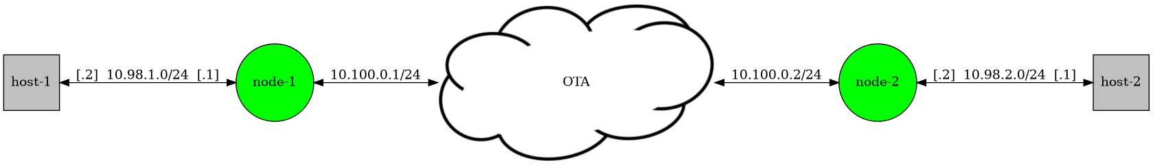
bentpipe-01 experiment components
The bentpipe-01 example contains two ground nodes, each with a host hanging off their respective lan0 interface. Both nodes use a single transponder in process mode.
All physical layers are configured to use the precomputed propagation model and emaneeventservice publishes PathlossEvents using the values in pathloss.eel.
0.0 nem:1 pathloss nem:2,87.0
emane-guide/examples/bentpipe-01/pathloss.eel
This experiment illustrates the versatility of the Bent Pipe model in process mode, allowing its use in a similar fashion as you would the RF Pipe radio model.

With emane-guide/examples/bentpipe-01 running, we can query node-1 to take a look at its transponder configuration.
$ emanesh node-1 get table nems mac TransponderStatusTable TransponderStatusExTable  AntennaStatusTable
nem 1   mac AntennaStatusTable
| Index | Profile | Bandwidth | Rx Frequency | Fixed Gain | Azimuth | Elevation | Mask |
| 0     | NA      | 150000000 | 29910000000  | 0.5        | NA      | NA        | 0    |

nem 1   mac TransponderStatusExTable
| Idx | Tx U_Delay | Tx Slots/Frame | Tx Slot Size | MTU  |
| 0   | 0          | 0              | 0            | 2048 |

nem 1   mac TransponderStatusTable
|Idx|Rx Hz      |Rx Bw    |Rx Ant|Rx Enable|Action |Tx Hz      |Tx Bw    |Tx Bps   |Tx Ant|Tx dBm|Tx Enable|
|0  |29910000000|150000000|0     |on       |process|29910000000|150000000|200000000|0     |0.0   |on       |
From these tables we see that node-1 has an ideal omni antenna with a fixed gain of 0.5 dBi using the default spectral mask; a single transponder tuned to transmit and receive at 29.910 GHz with both a transmit and receive bandwidth of 150 MHz; receives and transmits using the same antenna; uses no-protocol channel access, and is configured in process mode. Querying node-2 will show similar configuration.
We can verify connectivity between the attached lan0 hosts using ping:
$ ssh host-1 ping -R -c 5  host-2-lan
PING host-2-lan (10.98.2.2) 56(124) bytes of data.
64 bytes from host-2-lan (10.98.2.2): icmp_seq=1 ttl=62 time=1.23 ms
RR:     host-1-lan (10.98.1.2)
        radio-1 (10.100.0.1)
        radio-2-lan (10.98.2.1)
        host-2-lan (10.98.2.2)
        host-2-lan (10.98.2.2)
        radio-2 (10.100.0.2)
        radio-1-lan (10.98.1.1)
        host-1-lan (10.98.1.2)

64 bytes from host-2-lan (10.98.2.2): icmp_seq=2 ttl=62 time=2.23 ms    (same route)
64 bytes from host-2-lan (10.98.2.2): icmp_seq=3 ttl=62 time=2.33 ms    (same route)
64 bytes from host-2-lan (10.98.2.2): icmp_seq=4 ttl=62 time=2.15 ms    (same route)
64 bytes from host-2-lan (10.98.2.2): icmp_seq=5 ttl=62 time=2.18 ms    (same route)

--- host-2-lan ping statistics ---
5 packets transmitted, 5 received, 0% packet loss, time 4006ms
rtt min/avg/max/mdev = 1.231/2.023/2.325/0.400 ms
bentpipe-02
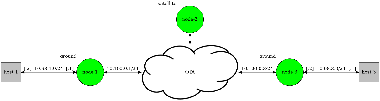
bentpipe-02 experiment components
The bentpipe-02 example experiment contains two ground nodes, each with a host hanging off their respective lan0 interface, and one satellite node.
The ground nodes have a single transponder, with node-1 using TDMA channel access and node-3 using no-protocol channel access. The satellite node has three transponders and three antennas. Transponder 0 uses a profile defined omni antenna, and transponder 1 and transponder 2 both make use of the other two directional antennas, where one antenna points at node-1 and the other at node-3. All satellite transponders use no-protocol channel access.
All physical layers are configured to use the freespace propagation model and emaneeventservice publishes LocationEvents using the locations in locations.eel.
# Carl Sagan final resting place
0.0 nem:1 location gps 42.4563980,-76.4930115,10.0

# satellite: somewhere over midwest USA
0.0 nem:2 location gps 46.349795,-100.219587,35786000.0

# area 51
0.0 nem:3 location gps 37.274043,-115.799030,10.0
emane-guide/examples/bentpipe-02/locations.eel

With emane-guide/examples/bentpipe-02 running, we can query node-2 to take a look at its transponder configuration.
$ emanesh node-2 get table nems mac TransponderStatusTable TransponderStatusExTable  AntennaStatusTable
nem 2   mac AntennaStatusTable
| Index | Profile | Bandwidth | Rx Frequency | Fixed Gain | Azimuth           | Elevation          | Mask |
| 0     | 2       | 150000000 | 29910000000  | NA         | 0.0               | 0.0                | 0    |
| 1     | 1       | 150000000 | 29745000000  | NA         | 94.34439424144891 | -86.98230090133954 | 0    |
| 2     | 1       | 150000000 | 29580000000  | NA         | 237.5217814216051 | -87.42647720511944 | 0    |

nem 2   mac TransponderStatusExTable
| Idx | Tx U_Delay | Tx Slots/Frame | Tx Slot Size | MTU  |
| 0   | 0          | 0              | 0            | 2048 |
| 1   | 0          | 0              | 0            | 2048 |
| 2   | 0          | 0              | 0            | 2048 |

nem 2   mac TransponderStatusTable
|Idx|Rx Hz      |Rx Bw    |Rx Ant|Rx Enable|Action|Tx Hz      |Tx Bw    |Tx Bps   |Tx Ant|Tx dBm|Tx Enable|
|0  |29910000000|150000000|0     |on       |ubend |20175000000|150000000|100000000|0     |54.0  |on       |
|1  |29745000000|150000000|1     |on       |ubend |20340000000|150000000|100000000|2     |54.0  |on       |
|2  |29580000000|150000000|2     |on       |ubend |20505000000|150000000|100000000|1     |54.0  |on       |
From these three tables we see that node-2 has three antennas, all of which are profile defined and use the default spectral mask; three transponders in ubend mode, where transponder 0 uses antenna 0 for receive and transmit, transponder 1 receives on antenna 1 and transmits on antenna 2, and transponder 2 receives on antenna 2 and transmits on antenna 1; and all transponders use no-protocol channel access.
The satellite node, node-2, does not have an attached host. Any over-the-air message it receives on a transponder will be relayed (bent) back over-the-air using the transponder’s associated transmit antenna.
Using ping to verify connectivity the same way we did in the bentpipe-01 example shows a less than complete topology picture due to the fact that the relay occurs in the radio model not node-2’s kernel space, so route records for node-2 are not added to the ICMP messages.
$ ssh host-1 ping -R -c 5  host-3-lan
PING host-3-lan (10.98.3.2) 56(124) bytes of data.
64 bytes from host-3-lan (10.98.3.2): icmp_seq=1 ttl=62 time=967 ms
RR:     host-1-lan (10.98.1.2)
        radio-1 (10.100.0.1)
        radio-3-lan (10.98.3.1)
        host-3-lan (10.98.3.2)
        host-3-lan (10.98.3.2)
        radio-3 (10.100.0.3)
        radio-1-lan (10.98.1.1)
        host-1-lan (10.98.1.2)

64 bytes from host-3-lan (10.98.3.2): icmp_seq=2 ttl=62 time=484 ms     (same route)
64 bytes from host-3-lan (10.98.3.2): icmp_seq=3 ttl=62 time=482 ms     (same route)
64 bytes from host-3-lan (10.98.3.2): icmp_seq=4 ttl=62 time=484 ms     (same route)
64 bytes from host-3-lan (10.98.3.2): icmp_seq=5 ttl=62 time=483 ms     (same route)

--- host-3-lan ping statistics ---
5 packets transmitted, 5 received, 0% packet loss, time 4002ms
rtt min/avg/max/mdev = 482.364/580.068/966.982/193.458 ms
We can verify the topology using the NeighborStatusTable for all 3 nodes.
$ for i in $(seq 1 3); do emanesh node-$i get table nems mac NeighborStatusTable; done
nem 1   mac NeighborStatusTable
|NEM|Transponder|SINR_wma         |NF_wma             |Samples|SINR_avg         |NF_avg             |Timestamp       |
|2  |0          |11.29777283855799|-118.63908740944319|7      |11.29777283855799|-118.63908740944318|1686943938679630|

nem 2   mac NeighborStatusTable
|NEM|Transponder|SINR_wma         |NF_wma             |Samples|SINR_avg         |NF_avg             |Timestamp       |
|1  |1          |8.066688845808386|-118.63908740944319|7      |8.066688845808386|-118.63908740944318|1686943938801503|
|3  |2          |8.137849777137916|-118.63908740944319|7      |8.137849777137916|-118.63908740944318|1686943938558921|

nem 3   mac NeighborStatusTable
|NEM|Transponder|SINR_wma          |NF_wma             |Samples|SINR_avg          |NF_avg             |Timestamp       |
|2  |0          |11.390794198620853|-118.63908740944319|7      |11.390794198620853|-118.63908740944318|1686943938921888|
Taking a look at node-2, we see that it sees node-1 on transponder 1 and node-3 on transponder 2. Both node-1 and node-2 see node-3 on their respective transponder 0.
We can use emanesh and change the frequencies of all three nodes in order to switch the ubend on node-2 to transponder 0, which uses the profile defined omni antenna, antenna 0.
$ emanesh node-1 set config nems mac \
   transponder.receive.frequency=0:29.910G \
   transponder.transmit.frequency=0:29.910G
nem 1   mac  configuration updated

$ emanesh node-2 set config nems mac \
    transponder.receive.frequency="0:29.910G,1:29.745G,2:29.580G" \
    transponder.transmit.frequency="0:29.910G,1:20.340G,2:20.505G"
nem 2   mac  configuration updated

$ emanesh node-3 set config nems mac \
    transponder.receive.frequency=0:29.910G \
    transponder.transmit.frequency=0:29.910G
nem 3   mac  configuration updated
Notice how even though we only want to change the frequency of node-2’s transponder 0, we still have to specify values for all three transponders since transponder.receive.frequency and transponder.transmit.frequency are configuration parameters that hold multiple values.
Similarly, if we want to change the antenna associated with node-2’s transponder 0 to an ideal omni, we need to specify the other antenna defines still in use:
$ emanesh node-2 set config nems mac \
    antenna.defines="0:omni;24.25;0,1:1;94.34439424144891;-86.98230090133954;0,2:1;237.5217814216051;-87.42647720511944;0"
Repeat the same ping command to verify connectivity.
$ host-1 ping -R -c 5 host-3-lan
Looking at node-2’s AntennaStatusTable and NeighborStatusTable, we can see that antenna 0 is now an ideal omni indicated by the NA in the Profile column, and node-2 sees node-1 and node-3 via transponder 0.
$ emanesh node-2 get table nems mac NeighborStatusTable AntennaStatusTable
nem 2   mac AntennaStatusTable
| Index | Profile | Bandwidth | Rx Frequency | Fixed Gain | Azimuth           | Elevation          | Mask |
| 0     | NA      | 150000000 | 29910000000  | 24.25      | NA                | NA                 | 0    |
| 1     | 1       | 150000000 | 29745000000  | NA         | 94.34439424144891 | -86.98230090133954 | 0    |
| 2     | 1       | 150000000 | 29580000000  | NA         | 237.5217814216051 | -87.42647720511944 | 0    |

nem 2   mac NeighborStatusTable
|NEM| Transponder| SINR_wma         | NF_wma             | Samples| SINR_avg         | NF_avg             | Timestamp       |
|1  | 0          | 8.018640050401672| -118.63908740944318| 908    | 8.018640050401698| -118.63908740944602| 1687204399299503|
|1  | 1          | 8.066688845808386| -118.63908740944318| 38     | 8.06668884580838 | -118.63908740944319| 1687203545323503|
|3  | 0          | 8.041484909729036| -118.63908740944318| 909    | 8.041484909728947| -118.63908740944602| 1687204400057385|
|3  | 2          | 8.137849777137916| -118.63908740944318| 38     | 8.137849777137921| -118.63908740944319| 1687203545081237|
The NeighborStatusTable does not delete entries. Use the Timestamp column value to determine an entry has gone stale, i.e. not updated in some time.